What is bitumen melting machine?
Bitumen melting machine is a device used in the construction industry to heat and melt bitumen, the bitumen is commonly used in road construction and roofing applications. The melting machine is essential for preparing bitumen for various construction processes.
Which grade of bitumen are meltable?
Common penetration grades include penetration grade bitumen 60/70, 80/100, and 120/150.common viscosity grades include vg-10, vg-20, vg-30, and vg-40.common performance grades include pg 58-28, pg 64-22, and pg 70-22.
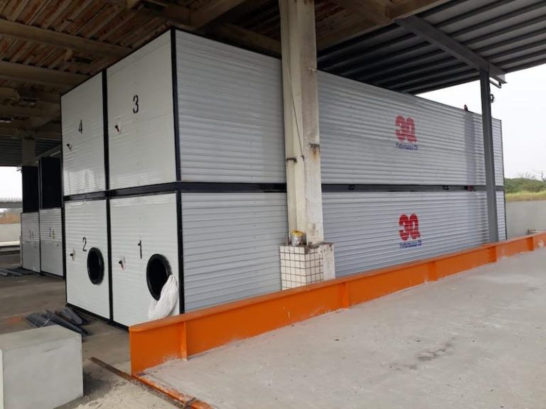
Packing of bag melting machine by treeq 3q
L × w × h = 11.8 × 2.25 × 2.2m, the melting box is 10.8m long, and the control area is 1m long. The safe volume is 30.5 m3. It can be loaded into 40hq high container, and the part affecting the packing can be disassembled.
Note: a set of melting machine is incluidng self melter and store unit which is 2x40ft along with axilaries.
Descreption of bitumen melter:
Item production plan
Remark
Quantity diesel oil burner self heating bag bitumen melting equipment, length 11.8 meter,storage tank 1 set
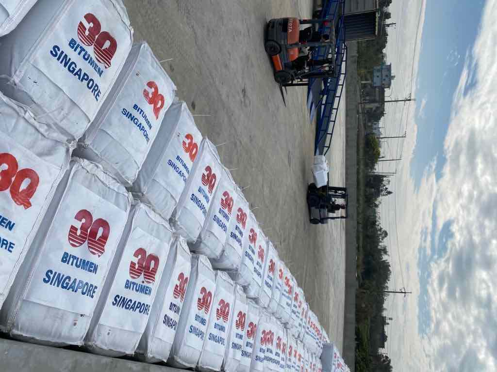
Bitumen melting equipment is specially designed for the melting and heating of 1 ton bitumen bag . The outside shape is cuboid tank. One end of the top of the equipment is equipped with the feeding port and the feeding platform. The block asphalt taking out from the bag is placed on the feeding platform by a forklift, and then the asphalt block is turned into the feeding port by a forklift. A gas collecting shield is arranged above the feeding port to facilitate the collection of waste gas through the waste gas treatment equipment.
Main technical parameter list of bitumen melter:
Item unit parameter remark
Product rate ton/hour 8-10 25° air over 25°
Diesel consumption kg/per ton 6-8
Asphalt output temperature >110
Asphalt storage capacity m³ >30
Thermal oil working temperature 200-250
Asphalt pump flow rate ㎡/h 42.8
Total power kw 50.5
Outer size(length*width*height) m 11.8×2.25×2.2
1-shape
Drag hook is added to the front base of the equipment.
2- feeding port
The feeding port of the equipment is set at one end of the device, and the inner diameter of the feeding port is long × wide
=2500×1950mm。
A gas collecting hood is arranged above the feeding port. Air collecting hood length×width×height
=2500×2150×1700mm,the frame is punched with 6# angle steel φ14mm for screws
Install. The air collecting hood is made to be disassembled into three independent pieces, assembled with screws on site, and the joints of each assembly are sealed with rubber strips.
- The sealing plate of the gas collecting hood is packaged with an iron plate with a thickness of 4mm.
The feeding port of the equipment is set at one end of the equipment, and the inner diameter of the feeding port is 2500 × 1950mm.
A gas collecting hood is arranged above the feeding port. Length × width × height of gas collecting hood:
2500 × 2150 × 1700mm, the frame is perforated with 6 # angle steel φ 14mm for screw installation. The gas collecting hood is made of 3 pieces which can be disassembled into independent ones, assembled with screws on site, and each assembly butt joint surface is sealed with rubber strips.
- The sealing plate of gas collecting hood is sealed with 4mm thick iron plate.
3- isolation net
A filter screen is set 3 meters away from the end of the feeding port, and the aperture of the filter screen is about 3cm. Strainer to do
To the bottom of the equipment, the height is 1050mm, and the upper part of the filter net is completely closed with a 4mm iron plate.
An isolation net with holes each diameter about 3cm is set at the place 3m from the feeding port end. The filter screen shall be at the bottom of the equipment with a height of 1050mm. The filter screen shall be completely sealed by 4mm iron plate.
4- heating system
There is a set of fuel oil self-heating furnace body assembly in the melting tank, equipped with italian 105p diesel burner. The combustion chamber is below the feeding port, and the outside of the combustion chamber and the main flue is covered by a heat-conducting oil layer
The package can supply high-temperature heat transfer oil to the outside world.
The melting tank is equipped with a set of diesel oil fired self heating furnace body assembly and an italian 105p diesel burner. The combustion chamber is under the feeding port, the combustion chamber and the main flue are wrapped by the thermal oil jacket layer, which can supply high temperature hot thermal oil.
5-thermal oil system
The equipment is equipped with a 50-50-150 heat transfer oil circulation pump with a flow rate of 24m³/h.
There are 2 sets of internal heat conduction oil heating coils, the pipeline is divided into three loops, and the part of the feeding port
1 channel can circulate independently, the 1 channel at the rear of the equipment can circulate independently, and the two coils in series can circulate as a whole. Pipe diameter: dn50.
There are two layers of triangular tubes on the upper part of the feeding port, with a gap of 200mm, in an inclined state, and the coil tube dives 300mm from the proximal end of the feeding side, and 400mm from the far end.
At the front of the equipment, there are 1 group of coils with 5 layers in total. The upper and lower coils are staggered and seamed, and there is one set at the rear of the equipment. There is no need to stagger the 3-layer coils.
The material of the upper coil cross bracing is 60×120mm square tube.
The equipment is equipped with a 50-50-150 thermal oil pump with a flow rate of 24m3 / h.
There are two sets of internal heat-transfer oil heating coil groups. The pipeline is divided into three loops. One loop at the feeding port can be recycled independently, one loop at the rear of the equipment can be recycled independently, and two loops of coil in series can be recycled as a whole. Pipe diameter: dn50.
The upper part of the feeding port is provided with two layers of triangle pipes, with a gap of 200mm, in an inclined state. The coil pipe is 300 mm from the near end of the feeding side and 400 mm from the far end.
At the front of the equipment, there is a group of coils with 5 floors in total. The upper and lower layers of coils are staggered to press joints, and a group of coils are set at the rear of the equipment, with 3 layers of coils without staggered. The cross brace material of the upper coil is 60 × 120mm square tube.
6-bitumen system
The equipment is equipped with 2 asphalt pumps, both of which have an inlet and outlet diameter of dn100.
An internal circulation asphalt pump is installed on the top of the equipment.
At the end of the head internal pipe of the top internal circulation asphalt pump, 7 dn32 horizontally arranged holes are opened from dn100.
- Another asphalt pump communicates with the storage tank, and can be flexibly controlled through the three-way valve
In the pipeline. The asphalt can be pumped from the melting equipment to the storage tank, and the asphalt in the storage tank can also be pumped back to the melting equipment.
Bitumen can also be pumped from storage tanks or melting equipment for external supply.
The equipment is equipped with 2 sets of asphalt pumps with inlet and outlet diameters of dn100.
One internal circulation asphalt pump is set at the top of the equipment.
At the end of the inner pipe of the head of the top inner circulating asphalt pump, 7 holes arranged horizontally by dn32 are opened by dn100.
- The other asphalt pump is interconnected with the storage tank, which can be flexibly controlled through the three-way valve of the pipeline. The asphalt can be pumped into the storage tank from the melting equipment, or the tank asphalt can be pumped back to the melting equipment. The asphalt can also be pumped out from the storage tank or melting equipment.
Bitumen storage tank brief introduction
Bitumen cuboid tank is used to store liquid asphalt, which can be heated and insulated.
Dimension
- It is a cuboid box. The overall dimension: l × w × h = 11.8 × 2.2 × 2.2m. It can be loaded into 40hq high container, and the part affecting the packing can be disassembled.
- The length of equipment box is 11.8m, one end is equipped with floating ball pointer and thermometer, the base is equipped with towing hook, the other end is equipped with dn150 asphalt connecting pipe flange and dn50 heat transfer oil connecting pipe flange. One end of the asphalt flange enters the container first when loading the container.
Thermal oil system
- One set of thermal oil coil is installed at the bottom of each oil storage tank, with two layers in total. The pipe diameter is dn50 and the length is about 240m.
- The flange is reserved at the inlet and outlet of heat transfer oil. The location of the flange is convenient for each oil storage tank to connect with each other. The user can connect the pipeline on site.
Bitumen system
- The flange shall be reserved at the inlet and outlet of asphalt. The location of the flange is convenient for each oil storage tank to connect with each other. The user shall connect the pipeline on site.
- The diameter of asphalt interconnection port is dn150 (6 inches).
- No. 1 and no. 2 asphalt outlets are interconnected, no. 3 and no. 4 asphalt outlets are interconnected, and the interconnection outlets of each oil storage tank are set at the bottom of the oil storage tank.
- One external asphalt pump is shared by the oil storage tank and the melting equipment. See item 4 of the asphalt system project in the above-mentioned oil self heating bag asphalt melting equipment manufacturing scheme for the transmission mode.
Manhole, breathing hole
The manhole is arranged at the top and the manhole cover is provided with a breathing hole.
Main technical parameter list:
Item unit parameter remark
Volume m³ 45
Heating way thermal oil coils
Heating exchage area ㎡ 43
Asphalt storage capacity m³ >45
Thermal oil working temperature 200-250
Insulation(24h temperature drop) <15
Bitumen inlet and outlet mm dn100
Thermal oil inlet and outlet mm dn50
Outer size(length*width*height) m 11.8×2.2×2.2
Configuration:
The inner wall of the tank is made of 5mm thick q235b carbon steel plate, the side wall reinforcement frame is made of 10# channel carbon steel, and the base frame is made of 12# channel carbon steel.
Thermal oil heating coil adopts 57×3.5mm gb/t8163 fluid seamless steel pipe.
The insulation is made of 100mm thick rock wool, and the outer wall is made of 0.5mm corrugated steel.